
China Best IQ Modulator Manufacturer and Supplier For Global Buyers

Choosing a China-based IQ Modulator manufacturer requires more than comparing prices or catalog specifications. Buyers should match the device to their operating band, modulation bandwidth, input power, and system interface. For example, a lab team may need stable sideband suppression across a wide frequency range, while a production line may value repeatable calibration and clear test records. Small differences matter.

Communications theorist Claude Shannon wrote, “The fundamental problem of communication is that of reproducing at one point either exactly or approximately a message selected at another point.” His principle helps explain why IQ balance, phase accuracy, and carrier leakage deserve careful attention. They shape how faithfully a modulator carries a signal through a real system.

A supplier’s datasheet is a starting point, not proof of performance. Ask for test conditions, measured results, temperature ranges, and support for integration. Check whether the manufacturer can explain how it verifies amplitude and phase balance, and whether its documentation matches the delivered unit. A polished brochure is not enough. Nor is the lowest quote always the best value.

This guide examines how global buyers can assess China’s IQ Modulator manufacturers and suppliers, compare technical capabilities, and identify practical questions before purchasing. No supplier is perfect. Even a strong candidate may have limits in lead time, customization, or technical support. Recognizing those trade-offs early makes sourcing decisions more reliable.
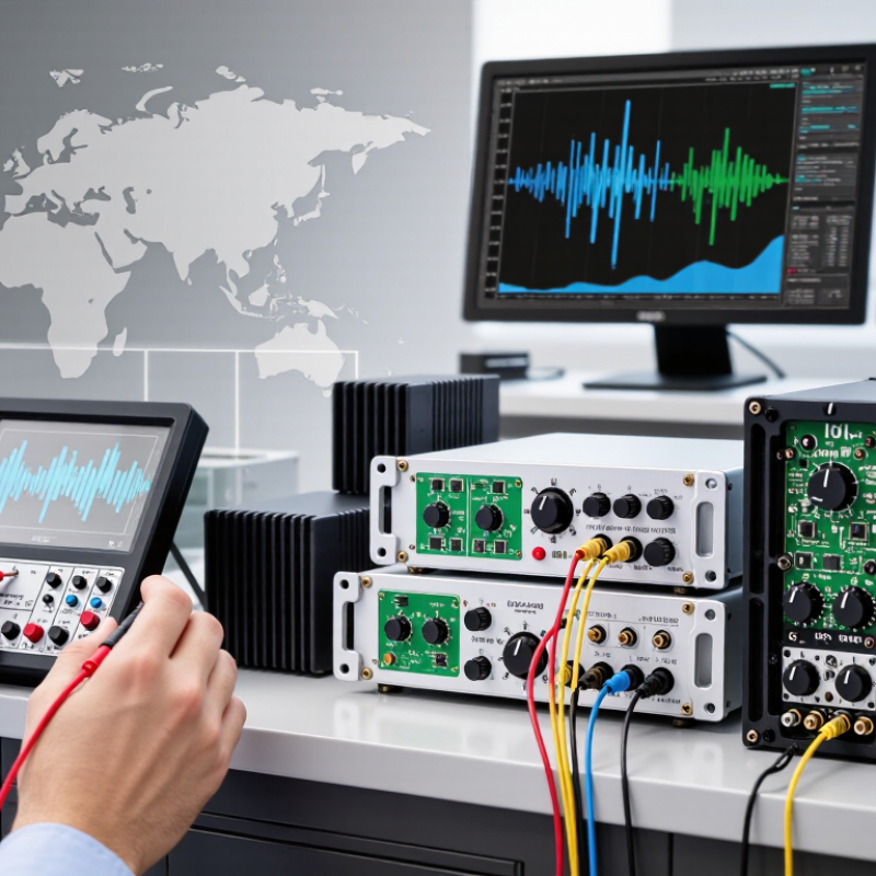
China Best IQ Modulator Manufacturer and Supplier For Global Buyers

What Is an IQ Modulator and How Does It Work?

An IQ modulator converts two baseband signals into a radio-frequency signal. These signals are called in-phase (I) and quadrature (Q). The device sends them through separate mixers while a carrier is split into two paths, with one path shifted by 90 degrees. Their outputs are then combined. By adjusting I and Q, the modulator can control the carrier’s amplitude and phase. That enables complex signal patterns.

In a digital system, samples from a converter feed the I and Q paths. A filter usually shapes the signal before it reaches the mixers. The resulting RF output depends on signal quality, timing, and the accuracy of the 90-degree phase shift. Even small gain or phase mismatches can cause unwanted distortion. On a test bench, engineers may check output power, spectrum, and image rejection. The practical answer is less tidy: results can change with frequency and temperature, so one measurement is rarely enough.

Tips: Check I/Q balance across the intended frequency range, not at one point only. Keep connections short and well matched. A clean-looking spectrum helps, but it does not tell the whole story.

Key Features and Applications of IQ Modulators

Key Features and Applications of IQ Modulators

An IQ modulator shapes an optical carrier by controlling two signal components, in-phase and quadrature. Their relative amplitude and phase can create complex modulation formats used in coherent transmission. Small errors matter. Bias stability, electrical bandwidth, insertion loss, and drive-voltage requirements all affect performance. A broad bandwidth rating alone does not guarantee a clean signal in a real system.

Engineers typically check the modulator’s operating wavelength, optical power handling, and bias-control method before integration. They also measure quadrature error and unwanted carrier or sideband leakage. Careful alignment and regular bias adjustment can help maintain signal quality, though laboratory conditions rarely match a deployed link perfectly. That difference is easy to underestimate.

IQ modulators are used in coherent optical communication, where they encode data onto light for transmission through fiber. They also support optical test benches, waveform generation, and some microwave-photonic systems. In a test setup, for example, an operator can adjust the drive signals and observe how phase and amplitude changes affect the output spectrum. Results depend on the full setup, including amplifiers, cabling, and measurement equipment. Not always predictable. A well-matched modulator makes calibration easier, but system-level testing remains essential.

How to Evaluate IQ Modulator Manufacturers in China

When evaluating IQ modulator manufacturers in China, ask for measured data, not polished promises. ITU’s Facts and Figures 2023 estimated that 5.4 billion people used the internet, or 67% of the global population. That figure signals expanding connectivity, but it is not a direct measure of modulator demand. For product fit, compare operating bandwidth, half-wave voltage, insertion loss, extinction ratio, and bias stability against your system requirements. IEEE 802.3df-2024 specifies 400 Gb/s and 800 Gb/s Ethernet capabilities, underscoring why high-speed optical designs need carefully matched components. Numbers matter.

Request test reports showing the setup, wavelength, temperature, and calibration method. Ask whether results represent one sample or a production batch; a single excellent unit proves little about consistency. Review fiber alignment, RF connector condition, and packaging details, too. Small details matter. If possible, test samples under your own drive conditions and check performance after thermal cycling. Compare promised lead times with documented production capacity and ask how failures are handled. An audit can still miss process variation, and I would not treat a certificate as proof of stable output. A clear, repeatable test record is stronger evidence.

China Best IQ Modulator Manufacturer and Supplier For Global Buyers - How to Evaluate IQ Modulator Manufacturers in China

Use this checklist to compare suppliers against your application requirements. Performance targets are system-dependent; request test conditions and supporting evidence rather than relying on headline figures alone.

Evaluation Dimension What to Check Evidence to Request Practical Evaluation
RF Frequency Coverage Specified operating frequency range, coverage gaps, and performance near the band edges. Current datasheet and measured results across the stated frequency range. Confirm that the complete required band is covered, including any necessary guard band.
I/Q Baseband Bandwidth Usable I and Q input bandwidth, amplitude flatness, and any stated group-delay limits. Frequency-response plots, test setup, and the conditions under which bandwidth is specified. Compare usable bandwidth and flatness with the intended signal bandwidth and waveform requirements.
I/Q Amplitude and Phase Balance Amplitude mismatch and phase error across frequency, operating level, and temperature. Measured balance data, calibration procedure, and clearly stated test conditions. Check whether the reported values meet your error-vector magnitude (EVM) or image-rejection requirements.
Carrier and Sideband Suppression Residual carrier and unwanted sideband levels, commonly reported in dBc under specified conditions. Spectrum-analyzer plots for defined input signals, with calibration and operating conditions recorded. Compare like-for-like measurements; suppression can vary with frequency, drive level, and calibration.
Conversion Loss or Gain Conversion loss or gain, frequency response, and variation with input and output levels. Datasheet specifications and measured conversion results for the intended RF and LO conditions. Check the impact on link budget and determine whether external amplification or attenuation is needed.
Linearity and Signal Handling Available linearity specifications, such as output 1 dB compression point and third-order intercept point, where applicable. Test reports that identify frequency, bias, drive level, and measurement method. Verify that the modulator can handle the required signal level while meeting spectral and distortion limits.
LO and Interface Requirements LO frequency and drive range, RF/LO/I/Q connector types, impedance, bias needs, and control connections. Interface-control document, pinout, electrical limits, and connection or integration guidance. Confirm compatibility with the system’s source, cabling, impedance, power, and mechanical layout.
Calibration and Repeatability Factory calibration, user calibration steps, required equipment, and stability after power cycles or temperature changes. Calibration instructions and repeatability results from repeated measurements. Assess whether calibration can be completed with available equipment and maintained in normal operation.
Environmental and Mechanical Fit Operating and storage temperature ratings, package dimensions, mounting, and connector durability. Mechanical drawings and environmental specifications for the offered configuration. Match ratings and dimensions to the installation environment; do not assume ratings beyond those documented.
Quality and Product Traceability Documented quality processes, inspection stages, serial or lot traceability, and change-control practices. Quality-system documentation, sample inspection records, and details of product revision control. Verify the scope and current status of any claimed certification with the issuing body where relevant.
Compliance Documentation Applicable safety, electromagnetic compatibility, and substance-restriction requirements for the destination market and product type. Relevant declarations, test reports, and supporting technical documentation for the specific product configuration. Confirm which requirements apply to the finished system; component-level documentation may not establish system compliance.
Production and Delivery Planning Available production capacity, order process, lead-time basis, and handling of schedule changes. Written quotation, delivery schedule, production status updates, and any stated capacity assumptions. Compare the supplier’s written plan with sample, qualification, and volume-production milestones.
Engineering and After-Sales Support Technical response process, support hours, troubleshooting resources, warranty terms, and repair or replacement procedures. Support policy, warranty terms, escalation contacts, and examples of technical documentation. Clarify response expectations and support coverage before placing an order, especially for custom configurations.
Sample and Qualification Process Availability of evaluation units, sample configuration control, and a process for moving from prototype to production. Sample quotation, acceptance criteria, evaluation plan, and documented revision history. Test representative samples against agreed specifications before approving the production configuration.

Comparison tip: Ask each supplier to quote the same configuration and report key measurements with frequency, temperature, drive level, calibration state, and test equipment identified.

What Global Buyers Should Check When Selecting a Supplier

When evaluating an IQ modulator supplier, compare the device specifications with your actual signal chain. Check operating frequency, modulation bandwidth, insertion loss, and I/Q amplitude and phase balance. Ask whether test data covers the conditions you will use, not just a convenient laboratory setup. A clear datasheet helps, but it cannot answer every integration question.

Tips: Request a sample test report and confirm its measurement conditions. Ask how units are calibrated and identified. Check connector type, lead time, and packaging before ordering. Ask for evidence. Small details matter.

Discuss technical support before a design issue becomes urgent. A reliable supplier should explain limitations plainly, respond to specific questions, and provide consistent documentation with each delivery. If possible, evaluate a sample in your own setup; cable loss and local equipment can change measured results. Price is easy to compare. Long-term consistency is harder. I would not treat one successful sample as proof that every future batch will behave identically, so agree on acceptance criteria and retain delivery records.

Ordering, Quality Control, and International Shipping Considerations

An IQ modulator order should begin with a written operating profile, not a product code alone. Specify wavelength, RF bandwidth, optical connectors, bias-control method, and expected drive levels. Small mismatches can affect system performance, even when the component appears suitable on paper. Details matter. Ask the supplier to confirm each requirement and flag any assumptions before production. Keep the approved specification with the purchase order; email threads can leave room for interpretation.

Quality control is easier to verify when acceptance criteria are agreed in advance. Request test records for key parameters, such as insertion loss, extinction ratio, and electrical response, where applicable. Ask how units are inspected and whether results are recorded against individual serial numbers. Test conditions matter. A value without its measurement conditions can be difficult to compare. In practice, specifications are sometimes incomplete, so buyers should review the report rather than assume every test matches their setup.

Before dispatch, confirm the shipping date, packaging method, and required commercial documents. Optical components should be protected from static, moisture, and impact; ask whether the package includes suitable cushioning and sealed inner bags. Send clear delivery details and confirm who will handle import charges and clearance. Allow extra time for international transit, especially when several handoffs are involved. A tracking number helps, but it does not prevent delays. Plan installation around the confirmed arrival window, not an optimistic estimate.

IQ Modulator Procurement: Illustrative Planning Timeline

Example working-day allowances for planning an international order. These are illustrative estimates, not supplier benchmarks: confirm production schedules, inspection requirements, and shipping times with your supplier and carrier.

Go to Top